Modern production lines require millisecond precision in coordinating hundreds of sensors and drives. A key element that manages these processes is the programmable logic controller, commonly called a PLC. Below we present how a PLC works and what its cycle looks like.
- What is a PLC controller and what is its role in a factory?
- What is the operating cycle of a PLC?
- The role of hardware components in the control process
- How does the method of programming affect the operation of the controller?
- PLC controller in a factory environment: Discrete system vs continuous control system
- Integration of the object-level with the supervisory level. Cooperation of PLCs with SCADA systems.
- FAQ – Frequently Asked Questions
What is a PLC controller and what is its role in a factory?
A programmable logic controller, known globally as a programmable logic controller, is a specialized industrial computer designed to operate in harsh conditions, such as high temperature, dust, or electromagnetic interference. This device continuously monitors the states of input devices and then, based on the stored program, makes decisions and generates control signals for actuators. In industrial automation PLC controller and what it is used for directly defines its hardware robustness and ability to operate continuously.
In contrast to standard IT systems, PLC controllers are characterized by strict time determinism, which means a guaranteed and repeatable response time to an event. These devices manage production lines, packaging machines, and even entire internal transport systems. We describe a complete comparison of how the relationship between PLCs and industrial computers looks in a dedicated study.
What is the operating cycle of a PLC?
A PLC operates on the principle of continuous, cyclical execution of a specified sequence of tasks that repeats in an endless loop. One full operating cycle of the PLC, sometimes called a scan, typically lasts from 1 to several dozen milliseconds, depending on the complexity of the algorithm and the CPU’s performance. Each operating cycle of the controller consists of four distinct, consecutive phases that ensure the logical consistency of machine control.
| Phase of the cycle | Operation name | Purpose of the operation |
| Phase 1 | Input reading | Sampling of the physical states of sensors and writing to the input image memory |
| Phase 2 | Execution of the program | Execution of successive lines of logical code by the central processing unit |
| Phase 3 | Update of outputs | Transfer of calculation results to physical output terminals |
| Phase 4 | Self-diagnostics and communication | Hardware tests and data exchange with external systems |
Phase 1: Reading inputs – input scanning
During the first phase of the cycle the central unit polls the physical input modules and records their states in a special area of RAM, referred to as the input image. In this way a snapshot of the machine’s state at a given moment is created, on which all subsequent logic processing is based. Any changes of signals on the digital inputs that occur during the execution of subsequent steps are not taken into account until the start of the next cycle, which eliminates the risk of logical instability.
Phase 2: Executing the logic program
In this phase the processor processes the program instructions step by step, using the data frozen in the input image memory. The control algorithm analyzes the stored logical states of the sensors and, based on them, calculates the new values that should be assigned to the outputs. At this stage a specific control system, automation, or logical sequence is implemented, and the results of the calculations are continuously written to the output image memory.
Phase 3: Updating outputs (scanning outputs)
The output update phase consists of physically copying the logical states from the output image memory to the controller’s real terminals. The output signal goes directly to the actuator modules, which causes an immediate response from the connected devices, such as valve solenoid coils, motor contactors, or relays. Only at that moment is the physical production process modified based on the logical decisions made.
Phase 4: Diagnostic tasks and communication
In the final phase of the cycle, the controller executes internal test procedures and handles communication requests. The device’s operating system checks memory consistency, power status, and the proper functioning of individual expansion modules. Simultaneously, the PLC controller performs the exchange of data packets with supervisory systems, HMI operator panels, and other devices operating on the industrial network.
The role of hardware components in the control process
The physical construction of a PLC determines how efficiently each operating cycle proceeds and how the device communicates with its environment. All hardware components, from the power supply to communication interfaces, work closely together to convert physical phenomena in the factory into mathematical and logical operations. We discuss the detailed classification of devices according to construction and types of PLCs separately in the post “what does a PLC controller consist of?.
Processor CPU and memory as coordinators of the cycle
The central processing unit (CPU) controls the entire process, clocking and synchronizing the successive phases of the operating cycle. The CPU fetches program instructions from ROM/Flash memory, while current process data and input/output image tables are stored in fast RAM. It is precisely the processor’s performance that directly affects the duration of a single scan cycle, which is crucial for fast industrial processes.
Input/output modules and signal converters
Input and output modules form a physical bridge between the processor logic and the devices on the site. An analog signal coming, for example, from a temperature or pressure sensor is converted by an analog-to-digital converter into a digital form that the processor can process. Conversely, output modules convert digital commands from the CPU into control signals, using galvanic isolation that protects the controller’s delicate electronic circuits from voltage surges.
Communication interfaces in the transmission of process data
Modern PLCs have built-in communication ports and modules that allow them to exchange data at speeds measured in megabits per second. Protocols such as Profinet, Modbus, or the classic RS-232 interface are used to transmit machine operating parameters to visualization systems and supervisory control systems. Stable communication allows the controller to be integrated with distributed I/O islands and with other controllers within a single plant network.
How does the method of programming affect the operation of the controller?
The way an engineer programs the controller has a direct effect on the cycle time and the load on the central processing unit. The choice of the appropriate method of writing logic – from graphical ones, such as ladder diagram (LD) or sequential function chart (SFC/Sequential Function Chart), to textual ones, such as structured text (ST) – defines the structure of the resulting code.
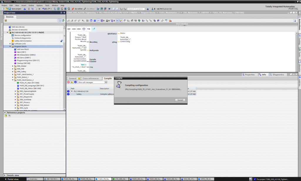
Programming of the PLC controller It is carried out using dedicated engineering environments, where the compiler translates the logic created by a human into machine instructions. An optimally written program shortens the scan time, which directly raises the reliability and responsiveness of the entire automation system. The programming standard, or if there is none, the engineer defines which PLC programming language It will be used to write code for the machine. It is possible that part of the code is written in one programming language, and part in another.
PLC controller in a factory environment: Discrete system vs continuous control system
In industrial settings controllers perform two basic types of control tasks, which differ in the nature of the signals processed. The first of these is a discrete system, in which control is based on two-state conditions (on/off, e.g. detection of the presence of a workpiece by a photoelectric sensor and stopping the conveyor).
The second variant is a continuous control (automation) system, where the controller implements an advanced algorithm (e.g., a PID loop), continuously reading digital and analog signals in order to precisely position a control valve or maintain a set temperature in a furnace. Simple controllers are also used in less demanding applications, a good example of which is an example for controlling traffic lights.
Integration of the object-level with the supervisory level. Cooperation of PLCs with SCADA systems.
The operation of PLC controllers at the lowest level of the automation pyramid is closely linked with higher-level monitoring and visualization systems. The device collects and aggregates key process parameters during each operating cycle, which it then makes available over the network to the SCADA system. Thanks to this, operators and management staff have a constant live view of the performance of production lines, emergency states, and machine performance statistics in real time. The cost analysis of implementing SCADA and automation systems in a production plant was presented in detail in a separate article.